
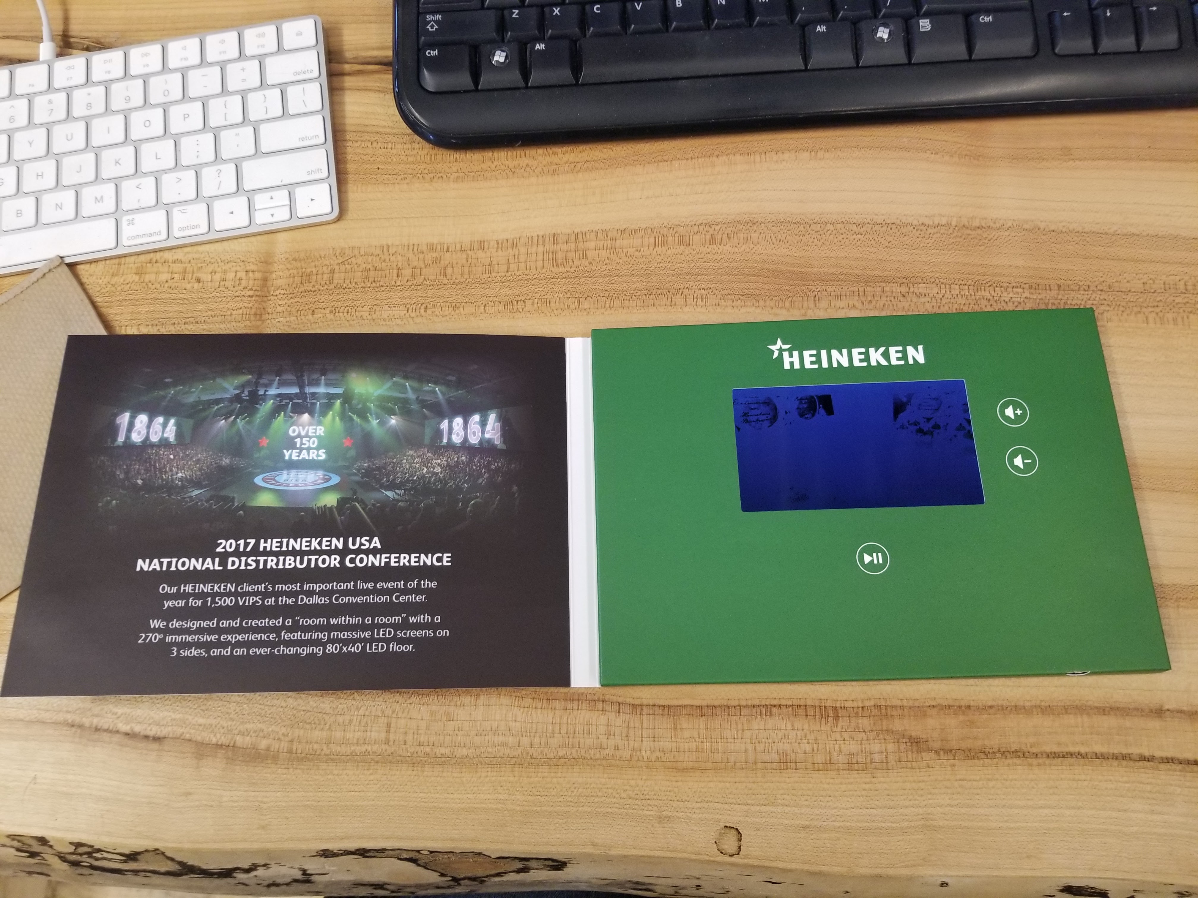
I recently came into possession of two video greeting cards: cardboard enclosures with a screen, processor and battery, that play a video when opened.
They are meant to be “disposable”, currently costing about $30-$40, and I wanted to see which components could be salvaged. That was ultimately fruitful – I got to keep a few goodies; also, though I didn’t quite get to reuse the processor unit itself, I did get closer to booting custom code than any of the previous documented attempts I could find.
There are a few existing articles tearing down this type of video greeting card:
- USB Device ID 1f3a:1000 Allwinner F1E200 electronic postcard
- https://www.igorkromin.net/index.php/2019/09/30/reading-console-output-from-the-e200-allwinner-based-video-brochure/
- Parts scavenging from promotional flyer w/video player
- Imgur album thread asking for hardware ident
- https://www.instructables.com/community/SerialConsole-Interface-for-Video-Brochure/
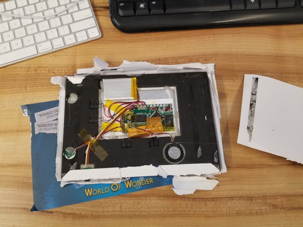
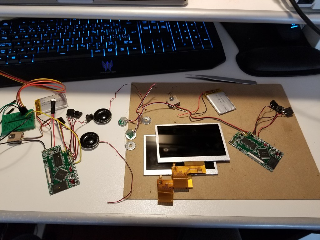
My salvage process found the same parts as in the above write-ups, netting the screen and battery from each card, as well as a magnet sensor, 4x buttons and 1x mini-USB socket per card.

In terms of hacking the main board itself, I was also able to tap into the UART TX pin, as described in the write-ups, and listen in on the boot communication. Since this board (possibly called Mayways) is running an Allwinner SoC called the F1E200, there is possibility of using the so-called FEL mode to intercept the boot process at a low level.
Other Allwinner SoC variants can be put into FEL mode by grounding the SPI CS pin (e.g. the F1C200 which powers the LicheePi Nano). The F1E200 has a SPI0_CS pin which multiplexes with NCE1 – NAND Flash chip enable. I found the counterpart chip enable pin on the NAND Flash chip and verified that the two are connected.
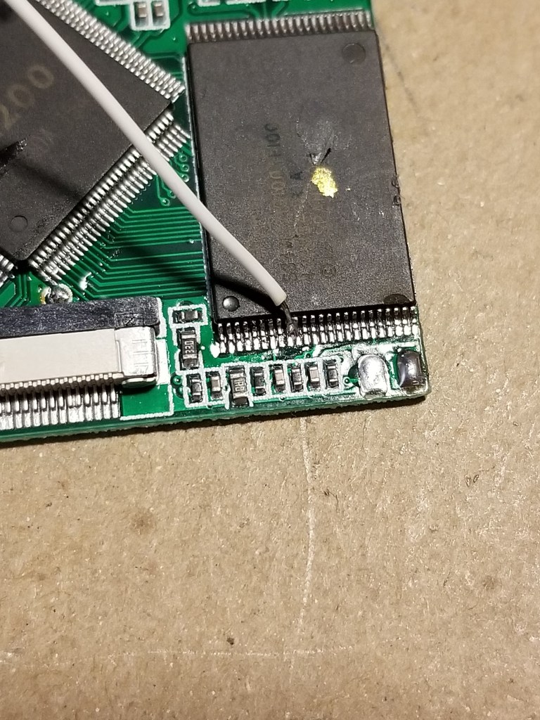
Then, I tried to solder a lead to the latter chip to try and ground it. It’s quite tricky with SMD components, so I had to compromise.
The neighbouring pin is marked not-connected, so I bridged the wire across the two leads (see picture). Then I powered it on via USB, without grounding that wire yet, and, unexpectedly, already could see the FEL mode activated!
This is the output of lsusb and the sunxi-fel utility now:
$ lsusb
Bus 001 Device 009: ID 1f3a:efe8 Onda (unverified) V972 tablet in flashing mode

$ sudo sunxi-fel version
Warning: no 'soc_sram_info' data for your SoC (id=1619)
AWUSBFEX soc=00001619(unknown) 00000001 ver=0001 44 08 scratchpad=00007e00 00000000 00000000
The UART serial output is gibberish only – oscilloscope showed a simple square wave burst at around 5us frequency, and that’s it. Probably because UART is not even used in this case, and the pin gets switched over to some other GPIO functionality.
When I tried to ground the soldered-on wire, the board actually did not boot at all – all I saw was repeating gibberish on UART (did not check scope) and did not see anything show up as a USB device at all.
And… well, that is about it. I tried to dump some data from memory and began looking into U-Boot support for the sun3i chip type (which is what F1E200 is listed under on the Sunxi website), but this is a whole new chapter of hardware hacking to take on. But I hope this can help someone more knowledgeable get to that next step of booting something more friendly on the hardware.
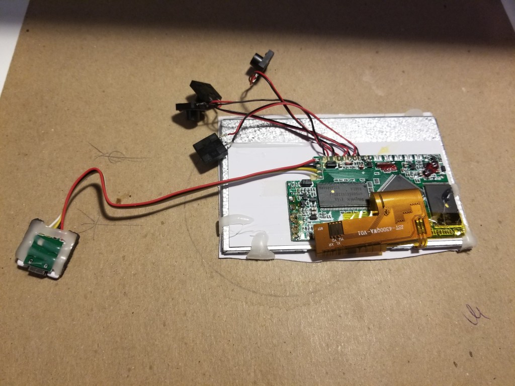
As a bonus, here is the salvaged TFT screen plugged into a LicheePi Nano (which has the same 40-pin connector):


You must be logged in to post a comment.